Links to other parts:
RC Control
As mentioned in part 5, i've purchased a Turnigy GT6 Surface radio. This radio (along with other Hobby RC units) outputs a pulsed signal to control the servos. I cant directly connect the RC receiver to the motors, i need to interpret the signals then drive the steering, brake, throttle on the bike.
I decided to use an Arduino Nano v3 for this task. It will be used as a translator between the RC receiver and the motors on the quad bike.
A high level diagram:
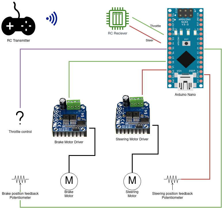
The intention is feed the RC receiver into the arduino, the arduino interprets the pulses and then reacts accordingly. i'm using the 'BTS7960 High power motor driver modules' to control the motors and 10K potentiometers for position feedback.
Getting Steering working
To start off, i've used some code that others have used to interpret RC signals.
There are two main methods of processing these signals on the arduino, PulseIn() function or assigning interrupts for the pins coming from the RC receiver.
-
PulseIn: is a simple enough function to use, however it is a blocking function. Meaning that while the PulseIn function is running, nothing else can be performed.
-
Interrupts: this is a far more complicated function however it allows for the arduino to be doing something else and when an interrupt gets triggered, the arduino will quickly process the signal and get back to what it was doing.
when i found that the PulseIn function was blocking, i started imagining the scenario where the bike is driving down the road and it gets stuck processing a signal causing the bike to crash into some bushes or something. I've settled on the Interrupt method as i believe it will be safer.
I wired up the steering motor, controller and RC receiver on my desk and using some basic "move a motor with an RC controller" code i found online.
Here's a short clip of the motor being used with positional feedback:
I'm using a 10K potentiometer (under the black square) with some scrap wire to link the motor and the pot.
I'm now confident that the steering is sorted out. i still need to mount it and make permanent wiring.
Throttle control
Throttle control is a tricky problem. i can see two different methods in getting this working:
-
install an R/C servo inside the throttle box to control the throttle sensor.
Pros: simple solution, R/C servo is cheap and easy to source.
Cons: servo would be an interference mechanism, meaning that in some cases the servo may hold the throttle open or prevent the thumb throttle from moving.
-
bypass the throttle box all together by re-generating the throttle signal.
Pros: non-interference solution since the throttle box is bypassed. A challenge.
cons: more complex, custom circuitry required, i have no experience with this method.
After some more research, i believe option two should be tried first and one can be the fallback.
Generating the throttle signal
I've tested the throttle box hall-effect sensor with my multimeter.
the sensor is generating a linear voltage range that is in relation to the distance from the magnets.
neutral: 3.5V
full throttle: 0.7V
I cant generate a voltage with an arduino, i can only generate a PWM signal. additional circuitry is needed.
My idea for this circuit is that the PWM signal from the arduino can be used to generate an analog signal by charging and discharging a capacitor.
I've created a test circuit on Tinkercad which i feel will do the job.
The waveform in the above video is not very smooth, it's more of a sawtooth. I don't think this will be an issue as the bike's speed controller is also a digital device.
The speed controller will be sampling the throttle sensor at a set frequency, i just need to tune my circuit to be smooth enough to trick the motor speed controller.
Schematic of the throttle signal circuit:
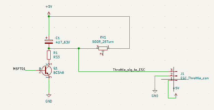
*msft01 is going to the arduino. I added a 500R multi-turn potentiometer to fine tune the output voltage.
Testing the throttle on the bike
I replicated the Tinkercad circuit onto a breadboard and took it into the workshop.
I used the R/C transmitter to control the PWM duty-cycle.
Here's a video of the throttle test.
Note the vibrations at full RPM, there's not much i can do about it. This bike is quite poorly built from the factory and those tyres need replacing...