I've been running the Solar system for a few years now without much trouble. Over time the battery capacity has slowly decreased to the point where the system gets dangerously low voltage overnight. The batteries I've been using are second-hand sealed "standby batteries" which were never designed to handle constant use and they already had been used for a few years before I bought them.
I've been connecting up a 24V battery charger on an ad-hoc basis over winter and sometimes have had to go turn it on before bed if I could see that the system wouldn't last the night.
I've only been using the system to charge power tools and run a deep freezer (surprisingly low power usage!). Due to the freezer turning on more when the weather heats up, i've found that the batteries just cant handle it any more.
I intend on replacing this ageing battery bank with a new-ish lithium bank that is correctly sized, however even second-hand cells are a little bit out of my budget for something that is pretty much just a hobby system. So in the meantime, I have a solution....
Relay controller
I like the whole IOT-controlled power outlets but I dislike the reliance on the internet/cloud servers due to security and reliability issues. I decided to create my own solution to this problem.
The features that I consider important for designing a home automation/IOT power control:
- wired connectivity
- The device must have a wired connection for communications. It can have a wireless control component but it cannot solely rely on wireless.
- Manual Over-ride
- The device must have a manual override, where you can turn on the outlet via a switch in the case where the internet/network isn't working or the "bus factor" occurs and someone else needs to turn on the device.
- simple function
- The device can be self-contained with some automation such as simple timers or similar. ideally, i want the device to only do what is expected of it and the smart stuff is moved onto a computer for better flexibility around the choice of software.
Designing the relay controller.
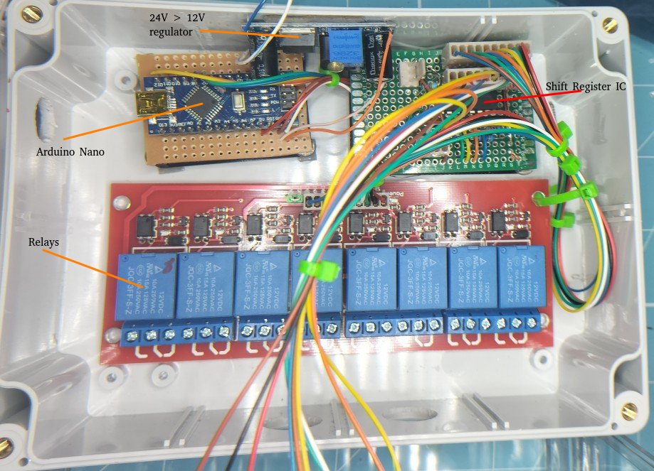
The relay controller will be based on an Arduino nano.
I've settled on using off-the-shelf hobby components with a little bit of a challenge to minimize the number of pins used on the Arduino.
Relay board:
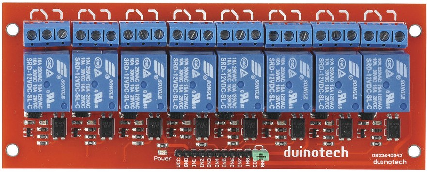
I picked up one of these hobbyist boards online. This board takes 1 pin for each relay. since the Nano has limited pins I don't want to waste valuable I/O on turning on and off a relay.
The relays are powered by 12VDC and the MOSFETs require 5V signals. I'll use a 24V to 12V regulator for the relays and for 5V signalling I'll use the 5V supply from the Arduino.
My solution to minimize pin usage is to use a shift register IC to power the relay pins. I've never used a shift register before but I'll figure it out.
Schematic
I did some googling, read some data sheets and watched some youtube about shift registers, they seem simple enough so I made a schematic of the circuit I want to make.
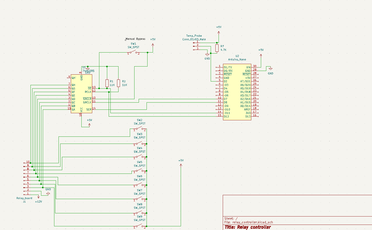
The shift register I decided to use was a 74HC595N 8bit tri-state CMOS IC which is a Serial-in/Parallel-out type.
In the above schematic, I've included 9 toggle switches. 8 switches for relays and 1 for 'manual-override' mode. in normal operation, the Arduino would be controlling the shift register. The Arduino would then take its commands via USB(Serial) connected to my raspberry pi.
Building the relay controller.
I've still not figured out how to create a PCB Mask and etch my own PCBs so it's protoboard again...
I, unfortunately, didn't get any good photos of the protoboard while I was making it.
For those with protoboard experience, I'm sure you can imagine what the solder tracks look like 😂.
I ended up damaging a few shift registers during the breadboarding process, I accidentally gave them 12V instead of their max input of 5V. 🤦♂️
It took me a while to figure out that I had damaged the IC since it would work if I manually shifted the bits in using push buttons to simulate the Arduino. But when I used the Arduino, the IC appeared completely dead.
implementing the relay controller
My plan is to use the solar analytics data that I've been collecting with my Raspberry Pi to determine when to turn on the battery charger while continuing to utilise solar power for the majority of the charging.
some Pseudo code that would run on the Raspberry Pi:
If PV_Voltage < 45.00 AND Battery_Voltage < 23.50
{
    Batt_charger = Enabled
}
Else
{
    Batt_charger = Disabled
}
This IF statement should only turn on the battery charger when the battery bank is Low and when the solar panels are not generating reasonable power. I'm expecting that this should cover most situations. Summer/Winter, Cloudy Days, solar panel fault, etc..
This doesn't account for the increased load from devices, though. I'll need to keep in mind what loads are being left on overnight and ensure I'm not exceeding the battery chargers rated current.
The 7 other relays are not in use yet, but I intend on adding more devices that can be programmed to utilise as much of the excess solar power as possible.
For example, I could use the relay controller to heat water during the day when there's excess power and then use it to provide hot water to the house.
it works!!
I implemented the first version of the scripts and the difference is pretty obvious.
Here's a graph of the battery voltage overnight, with no charger*:
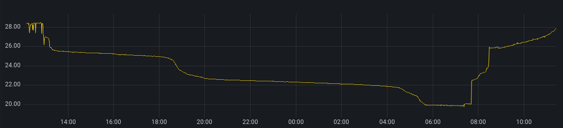 The voltage gets to 22V and as low as 20V just before sunrise.
This is way too low for lead-acid batteries and I'm sure this has done some damage.
The voltage gets to 22V and as low as 20V just before sunrise.
This is way too low for lead-acid batteries and I'm sure this has done some damage.
Here's the graph after I added the relay controller*:
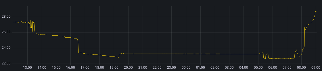
While the voltage does still dip to 23V (still not good) it now doesn't drop to < 22V overnight. I'll need to make some adjustments to allow the charger to turn on earlier to maintain a better voltage.
The small dip and spike between 0500hrs and 0600hrs is the solar panel voltage going over the threshold to keep the charger turned on. Some trees block the solar panels in the morning which would explain why the charger turns off and then back on a short time later.
Some Notes.
- *Keep in mind that all battery measurements on this page are measured under load which is not the right way to measure battery State of Charge. I should be doing quarterly capacity tests to get a better idea of the health of these batteries.
- The batteries were tested at 80% healthy when I bought them and that was a few years ago. These batteries don't have much life left, I'm just kicking the can down the road for a bit until lithium batteries/cells get a little cheaper which at this rate could be 6 months from now.
- The other benefit to using the relay controller over just connecting the battery charger full-time or on a timer is that this solution doesn't need adjustment when the seasons change. Because the charger isn't staying on full-time, the solar panels are doing the majority of the charging and the charger is acting as a safety buffer.
- I'm intending on publishing the code used on my personal Github in the future. I'll update this post with links when I do that.