I've been toying with small solar systems for 15 years or so.
My largest system so far:
- 800W of free solar panels
- 1KW MPPT Solar charger
- 400AH (used) standby batteries
- 2.5KVA Pure-Sine Inverter
I wanted to monitor my solar controller for solar predictions and load graphing.
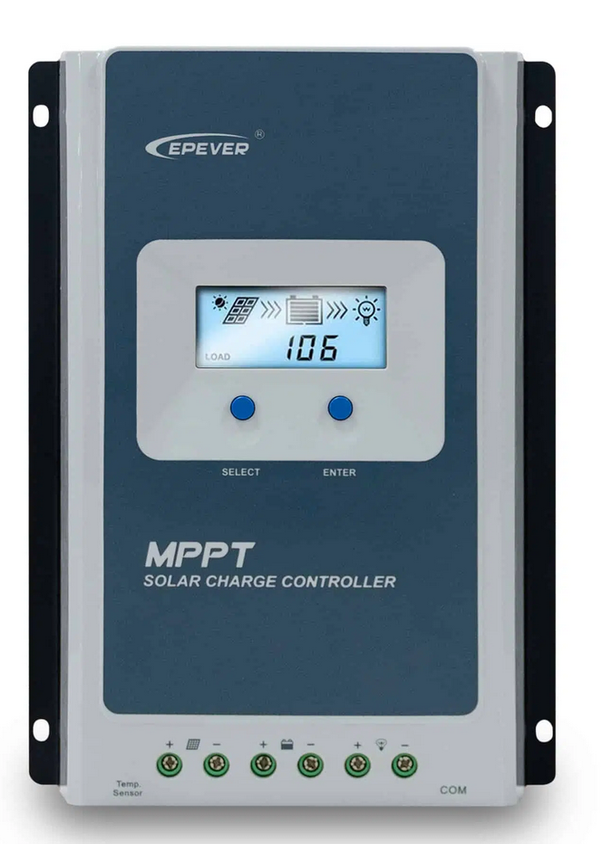
I purchased a Epever Tracer3210AN, which is a fantastic solar controller for price and functionality.
I purchased a combo from an eBay seller that included the 'Epever eBox-WIFI-01' WiFi unit. when i set all of this up and used the android app it worked great, however i wanted to capture this data and store it in influxDB with Grafana. i couldn't see an easy way to poll the WiFi module for the data.
further digging around using wireshark to man-in-the-middle the communications between the app and eBox i found that it wasn't using a "web-friendly" protocol like XML or JSON. the communications were instead MODBUS over TCP (later finding that it's actually MODBUS RTU over TCP).
a quick internet search i found that most people just connect the cable directly to their computer instead of messing about with the eBox. i have no idea about modbus other than it is a reliable protocol used in industrial applications heavily.
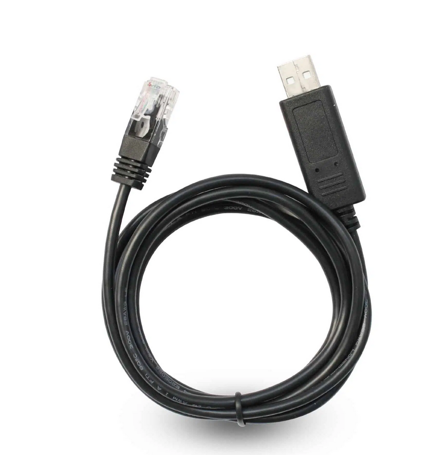
i ended up putting eBox on the shelf and buying a Epever RS485 to USB cable.
i connected it up to my raspberry pi, slapped together some code to poll the solar controller based off https://github.com/alexnathanson/EPSolar_Tracer repo.
This all worked great for about a year. I then hit the power limitations of running the solar system in a 12v configuration (390W@12V vs 780W@24v), so i purchased more batteries and changed the system to 24V.
When it all went wrong
I had just finished the wiring to upgrade to 24V and the batteries were charging fine.
i was running the Raspberry Pi off the batteries as well, tapping off one of the banks so i could still get 12v then feeding this through a car USB adaptor to get 5V for the Pi. i checked the voltages and 5v was coming into the Pi and it booted fine. I then plugged in the USB cable for the Epever comms, suddenly i heard a *pop* and could smell burning electronics. The pi was dead.
i couldn't figure out what was different (other than the obvious 12 -> 24V change). i had checked multiple times and the Pi power supply was still providing 5V.
i tried another pi after confirming the voltages and again *pop* magic smoke from the pi and this time the controller also put out a bit of smoke (controller still worked the comm port was smelly though??). i put down this project for a bit while i think about what had happened.
i eventually figured out that the comm port ground was grounded to the 24v ground and it must have been feeding the 24v ground into the raspberry pi via the USB port, killing the pi(s) almost instantly.
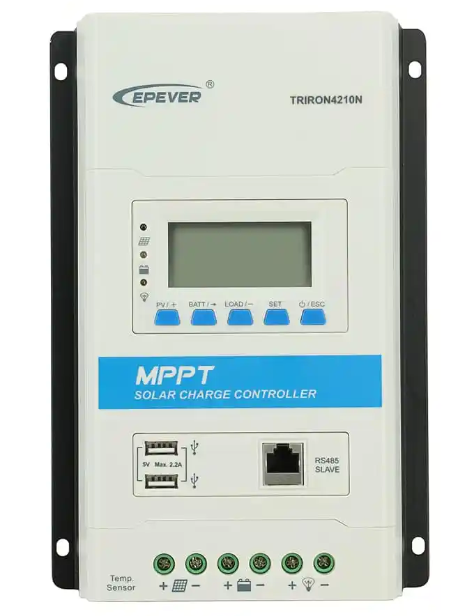
since i had broken the solar controller's Comm Port now as well, i reluctantly purchased another solar controller. i Purchased the Epever TriRon 4210N. Which is the newer model than the 3210AN.
This time i wasn't going to make the same mistake, i had to protect the comm port while also interfacing it with the raspberry pi. i looked into building a USB cable with opto-isolators but this was going to be a bigger task so i returned back to the eBox WiFi again.
i plugged in the WiFi module and opened the app, all worked good. Now i needed to somehow extract the data from the eBox and get it into the (new) raspberry pi.
So i opened up wireshark, got the Windows Epever software going using a 'virtual com port'. Reading the captured packets just confused me even with the wireshark "Decode As..." set to modbus.
More googling and i found that the python library 'pymodbus' also supported TCP mode. So i updated my code to use the ''ModbusTcpClient". no luck, i enabled debugging and no matter what i tried i couldn't get the eBox to send data at all or if it did it was invalid.
DEBUG:pymodbus.client.sync:Connection to Modbus server established. Socket ('11.11.11.3', 46349)
DEBUG:pymodbus.transaction:Current transaction state - IDLE
DEBUG:pymodbus.transaction:Running transaction 1
DEBUG:pymodbus.transaction:SEND: 0x0 0x1 0x0 0x0 0x0 0x6 0x1 0x4 0x32 0x0 0x0 0x3
DEBUG:pymodbus.client.sync:New Transaction state 'SENDING'
DEBUG:pymodbus.transaction:Changing transaction state from 'SENDING' to 'WAITING FOR REPLY'
DEBUG:pymodbus.transaction:Transaction failed. (Modbus Error: [Invalid Message] No response received, expected at least 8 bytes (0 received))
DEBUG:pymodbus.framer.socket_framer:Processing:
DEBUG:pymodbus.transaction:Getting transaction 1
DEBUG:pymodbus.transaction:Changing transaction state from 'PROCESSING REPLY' to 'TRANSACTION_COMPLETE'
Modbus Error: [Input/Output] Modbus Error: [Invalid Message] No response received, expected at least 8 bytes (0 received)
Above example of the errors i was getting.
I found this Stack Overflow post where OP was seeing a similar issue.
In here i spotted that OP was using a ModBus Framer. Not sure exactly what it does but i suspect it filters out the TCP/IP stuff before it's used by the client object.
I made 2 changes to my script and retried, this time it worked!!!
Here's what my script looked like before the Framer changes:
#!/usr/bin/python3

from pymodbus.client.sync import ModbusTcpClient as ModbusClient

client = ModbusClient('11.11.11.254' ,port=8088,timeout=5)
client.connect()

result = client.read_input_registers(0x3100,16,unit=1)

solarVoltage = float(result.registers[0] / 100.0)
solarCurrent = float(result.registers[1] / 100.0)
solarPowerL = float(result.registers[2] / 100.0)
solarPowerH = float(result.registers[3] / 100.0)
batteryVoltage = float(result.registers[4] / 100.0)
chargeCurrent = float(result.registers[5] / 100.0)
chargePowerL = float(result.registers[6] / 100.0)
chargePowerH = float(result.registers[7] / 100.0)
loadVoltage = float(result.registers[8] / 100.0)
loadCurrent= float(result.registers[9] / 100.0)
loadPower= float(result.registers[10] / 100.0)
batteryPercentage = float(result.registers[0] / 100.0)

# Do something with the data

print("PV Voltage: " + str(solarVoltage))
print("PV Current" + str(solarCurrent))
print("Battery Voltage: " + str(batteryVoltage))
print("Charge Current: " + str(chargeCurrent))
print("Load Current" + str(loadCurrent))
print("Load Power: " + str(loadPower))

client.close()
And after the addition of the Framer:
#!/usr/bin/python3

from pymodbus.client.sync import ModbusTcpClient as ModbusClient
from pymodbus.transaction import ModbusRtuFramer as ModbusFramer

client = ModbusClient('11.11.11.254' ,port=8088,timeout=5, framer=ModbusFramer)
client.connect()

result = client.read_input_registers(0x3100,16,unit=1)

solarVoltage = float(result.registers[0] / 100.0)
solarCurrent = float(result.registers[1] / 100.0)
solarPowerL = float(result.registers[2] / 100.0)
solarPowerH = float(result.registers[3] / 100.0)
batteryVoltage = float(result.registers[4] / 100.0)
chargeCurrent = float(result.registers[5] / 100.0)
chargePowerL = float(result.registers[6] / 100.0)
chargePowerH = float(result.registers[7] / 100.0)
loadVoltage = float(result.registers[8] / 100.0)
loadCurrent= float(result.registers[9] / 100.0)
loadPower= float(result.registers[10] / 100.0)
batteryPercentage = float(result.registers[0] / 100.0)

# Do something with the data

print("PV Voltage: " + str(solarVoltage))
print("PV Current" + str(solarCurrent))
print("Battery Voltage: " + str(batteryVoltage))
print("Charge Current: " + str(chargeCurrent))
print("Load Current" + str(loadCurrent))
print("Load Power: " + str(loadPower))

client.close()
Adding the Framer to the ModbusClient was what fixed it for me.
here's the output:
PV Voltage: 77.95
PV Current: 1.05
Battery Voltage: 27.52
Charge Current: 2.98
Load Current: 0.16
Load Power: 0.0
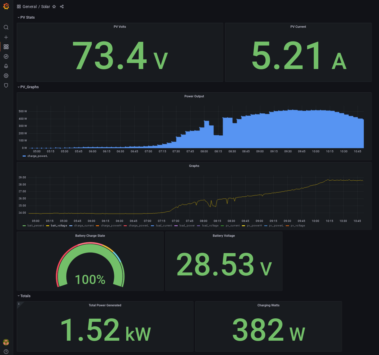
The solar data is now being sent to my local InfluxDB and Grafana instance.
In Summary
I recommend using the USB cable to poll the controller in most cases. If you're doing something like me where you're trying to get 12V from a 24V battery bank, either purchase the proper "24 to 12 converter" or make sure the 12V devices do not electrically interact with any 24V devices or you may kill the 12V device.
-
Running a 12V fridge directly off the 12V side of the 24V bank would be fine, if the fridge then connects to another device like a 24V powered fridge controller or something is where the danger arises.
-
Be aware that tapping 12V from one side of the 24V bank is going to cause an imbalance and probably shorten the life of the batteries. In my case, these are used batteries, so i don't care too much.